GROUND WATER INVESTIGATION

Our practice for well siting means finding the drilling site that yields water or offers alternatives at reduced cost. That’s the purpose for the Pre-drilling Hydrogeological Assessment that uses the HydroImage method or a combination of our technologies.

Ground Water and Aquifers

Our practice for well siting means finding the drilling site that yields water or offers alternatives at reduced cost. The purpose for the Pre-drilling Hydrogeological Assessment is to provide a “picture” a “HydroImage” of the below ground conditions.

    Groundwater investigations are completed for several reasons....
  • Site wells
  • Anticipate underground conditions prior to drilling, construction, or excavation
  • Produce geologic maps
  • Delineate underground aquifers, or
  • Locate groundwater contaminants
    Since groundwater mapping often overlaps with engineering investigations, mapping of the groundwater and the subsurface environment contributes to solving.....
  • Problems of drainage and water supply at construction sites
  • Problems related to slope stability, soil strength, and subsidence
  • Questions relating to water supply , such as pumpage and recharge, and
  • Subsurface geology of mineral deposits
Need to Site a Well? We Can Help.

The Pre-drilling Hydrogeological Assessment

Bob Tarbert (left), owner, Tarbert Well Drilling Inc., and Michael Hamilton (right), veteran geologist for Washington Department of Natural Resources.
    How this service helps:
  • Find water-bearing strata and the right drill site
  • Avoid drilling dry holes at sites lacking water storage
  • Identify and avoid “no-water” areas, non-aquifer rock strata
  • Identify low-cost options if a drilling target cannot be identified, or
  • Instruct driller to locate water and anticipate drilling conditions


A Pre-Drilling Hydrogeological Assessment – Actual Site Results
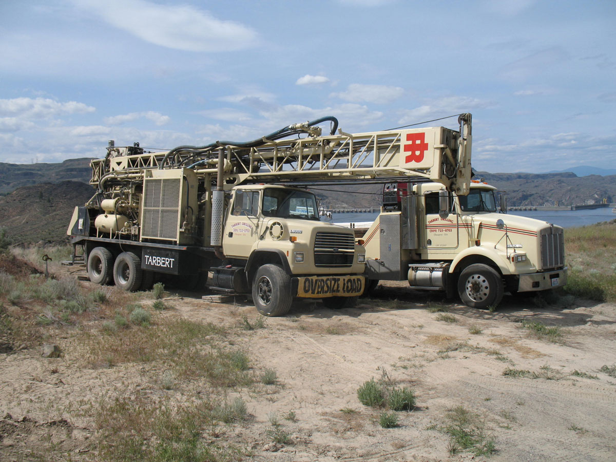
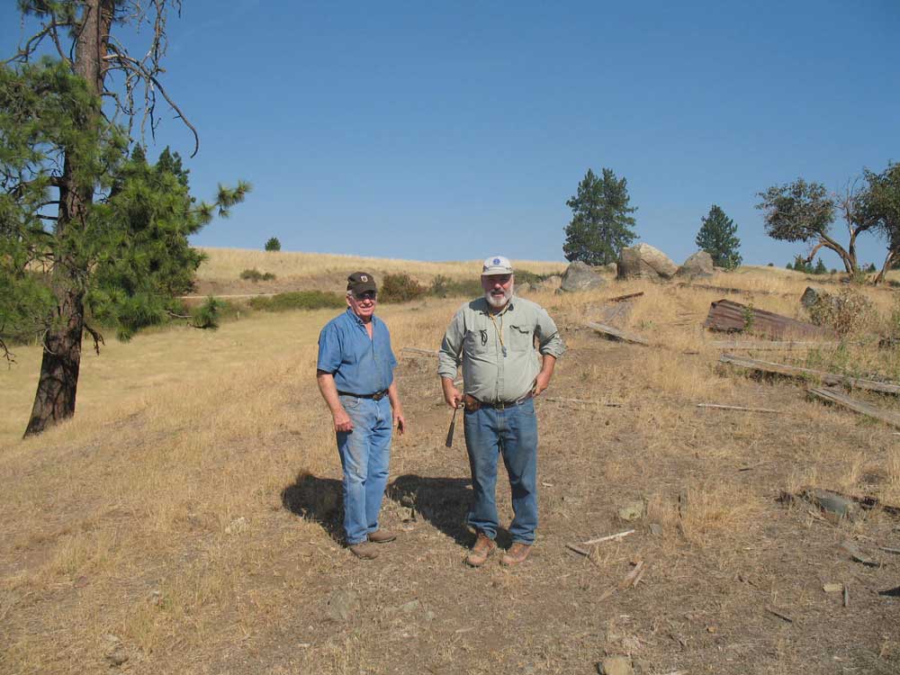
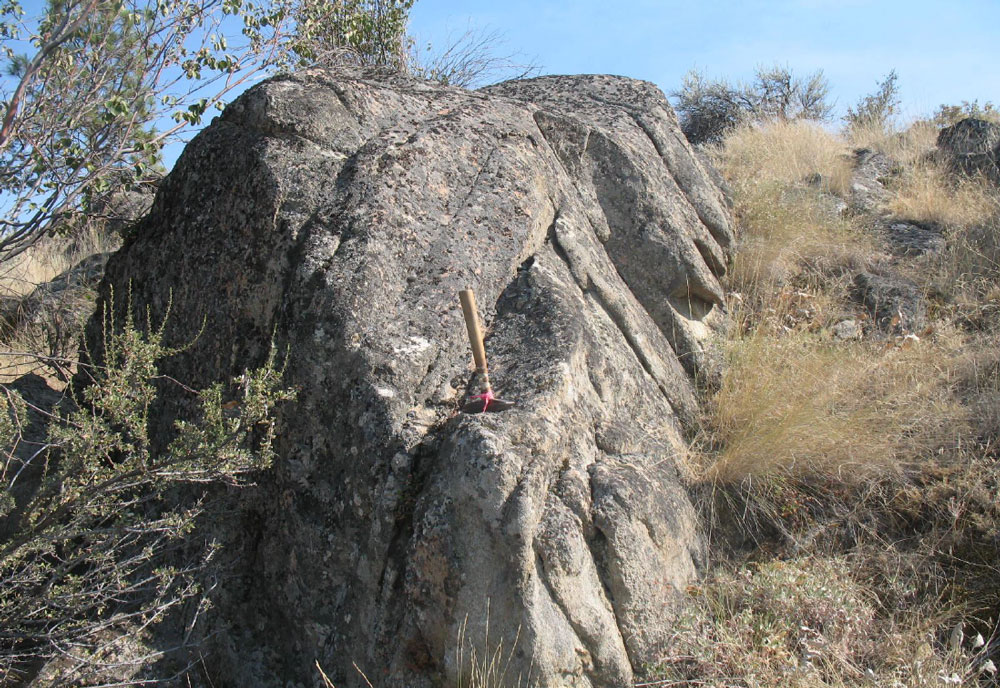
HydroImaging Inc. conducted an assessment using earth resistivity imaging technology at the site in Washington. Two previous wells nearby, included a 500 ft deep dry boring and a second 45-ft deep well that intermittently produced 5 gallons per minute but dried up in mid-summer when the garden vegetables required irrigating. Work by HydroImaging Inc. identified a target zone at a depth of 105-145 ft and located 297 ft north of the 45-ft well. Drilling at the recommended site resulted in a new well producing 11 gallons per minute that was converted as the garden’s primary water source. Besides finding water, the HydroImaging work explained the complex hydrogeologic character of rock strata underfoot, the likely lifetime of the new well and reasons to explain the unproductive nature of the older wells. The new well is located about 100 ft to right of photo. Details of Case Study 1


Who benefits?
  • Landowners, drillers, contractors, or home builders needing to locate a site for a domestic water well
  • Engineers and municipal water districts in need of a larger water source, and
  • Excavation contractors or anyone concerned about the impact of subsurface water conditions at construction sites


Is it affordable?
  • Improvements in portability, micro-processor control, high rate of acquisition of data, and laptop computer processing are factors that have significantly reduced the time and personnel needed to get results
  • Less time means lower cost to access this technology
  • Therefore, landowners, home builders, excavation contractors and others can now use Pre-drilling Hydrogeological Assessment for a reasonable cost


What Is It?
EARTH resistivity electrical imaging (ERI) is used to produce the HydroImage to produce an image of the water conditions.
Investigating Characteristics of Fluids (Aquifers) and Rock Materials from their Standard Electrical and Velocity Properties
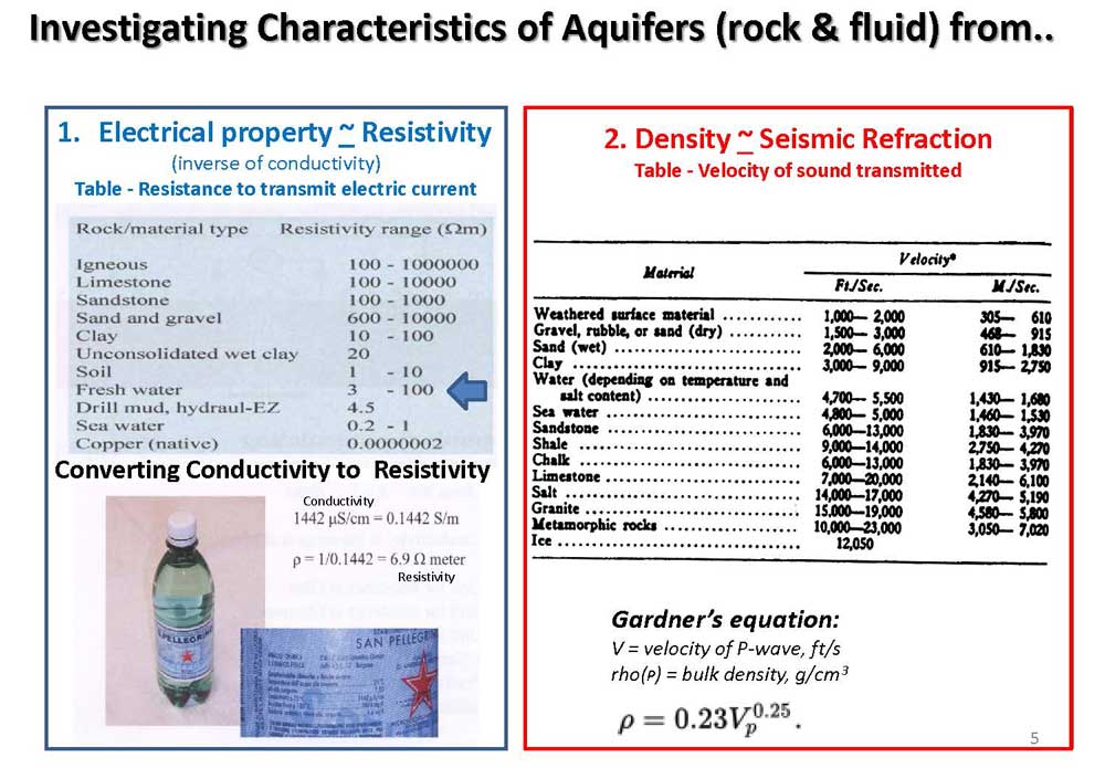
1. Electrical properties used to interpret electrical resistivity imaging data
2. Velocity (strength, density) properties used to interpret seismic refraction and shear wave (MASW) data.


History
The idea of using electrical resistivity to map subsurface rock features was originated by Marcel Schlumberger in 1912 in France. Marcel and Conrad Schlumberger patented the idea in 1923 and proceeded to map an oil field in Romania using the method. The method was applied in Europe, Canada, and U.S.A. in the late 1920s. It was soon modified to downhole surveying in boreholes in oil fields, eventually leading the brothers to the formation of the Schlumberger Well Surveying Company in 1935.


How It Works
Fractures found in granite bedrock offers a limited source of water (or no water) in wells drilled at rural home sites. Bedrock that exhibits a high degree of fracturing (top is a source of the highest yielding wells. Geophysical investigation methods available can locate the optimum drill sites. Finding water at rural home sites is commonly a challenge due to hard rock conditions that limit water flow rate from well. The nature of the hard, dense granite with little or no space to store water (lower image) is reason for difficulties.
  • Electrical resistivity operates by transmitting a very low electrical voltage and current from a deep cycle battery into the ground and measuring its differences at varying distances from the transmitting point. The rock resistivity is determined by the degree of diminution between points of the transmitter and receiver by Ohm’s Law. The technology allows constructing the HydroImage, a geologically-realistic model (image) of the resistive or conductive nature of the subsurface rock and water.
  • Success of ERI lies in rapidly acquiring hundreds of resistivity measurements to describe the rock strata underfoot. Changes in resistivity result from the varying level of saturation or lack of saturation of rocks by groundwater. Rock strata containing groundwater are excellent conductors of electricity assisted greatly by traces of minerals and dissolved salts. Even minute concentrations of these constituents permit an electrical connection through moist or water-saturated rock strata.


Strategy

A pre-drilling hydrogeological assessment yields important information about the location of water-bearing rock strata and sites to avoid that may result in dry holes. Our philosophy is that the landowner actively participates throughout the assessment, since the landowner is knowledgeable of the site, has special needs, and assumes ultimate responsibility.
Groundwater Exploration

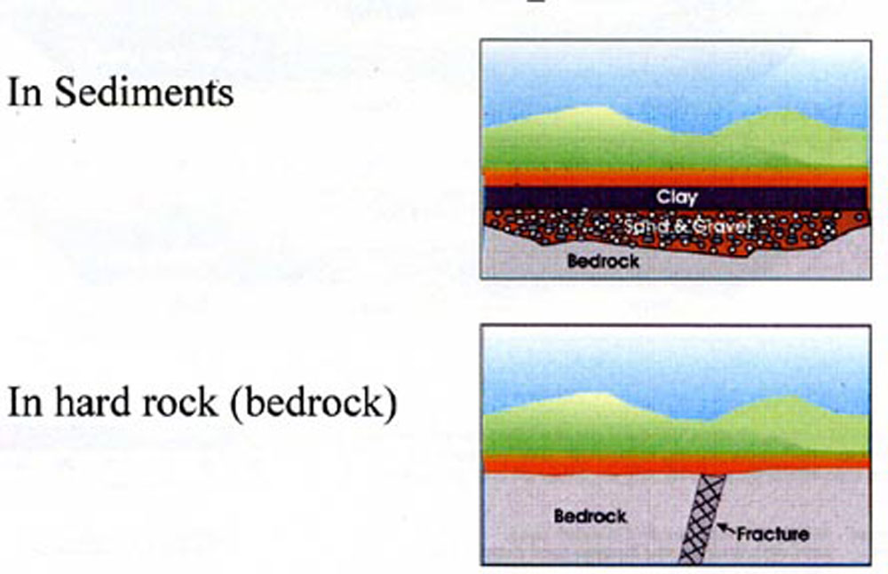
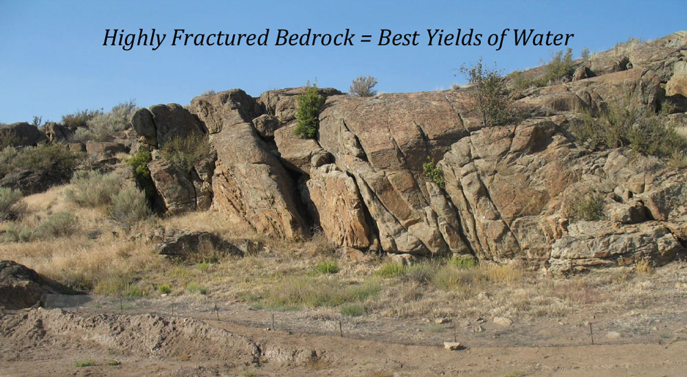
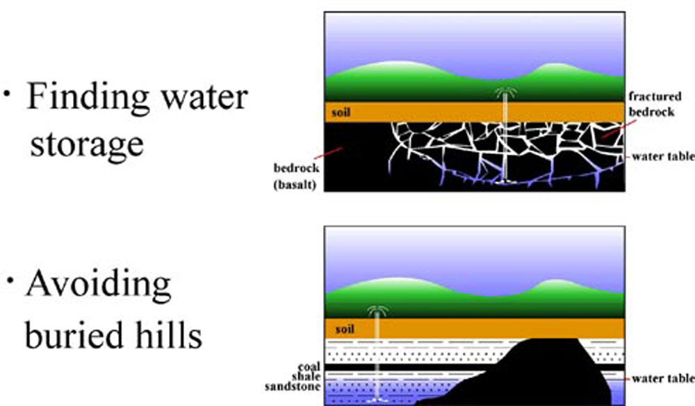
Groundwater exploration examples illustrate four conceptual aquifers, or models, that describe how groundwater occurs in the region. Water occupying the pore space between particles of sand, gravel, pebbles, and boulders is extremely common. Water in fractures or faults in hard rock (often granite bedrock) is a second situation also commonly encountered by rural water users.

The third is an example of fractures that provide a water storage within a fractured granite or basalt. (Case Study 2 – Four Mound Prairie shows ERI result identical to example 3). Case Study 3 - Earth Resistivity Profile provides a similar example although the water zones are contained in fractures within granite and gneiss.
A buried hill of granite in example four should be avoided
Need a Pre-drilling Hydrogeological Assessment?.....Contact Us